 175
175
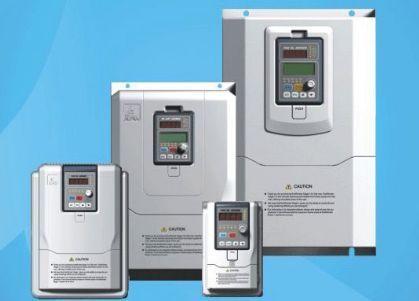
What is the frequency converter, in general: AC - DC - AC (can also be said to be rectified first - then inverter), after this processing process of the inverter is also called AC AC frequency conversion, is also used in various industries more. In addition, there is a kind of exchange-alternating transformation, which is also known as an alternating frequency converter.

First, what is a frequency converter
The frequency converter is a power control device that uses the on-off effect of power semiconductor devices to convert the power frequency power supply into another frequency. The frequency converter is mainly composed of rectification (AC to DC), filtering, inverter (DC to AC), brake unit, drive unit, detection unit, microprocessing unit, etc.
Frequency converter is to convert the power frequency power supply (50Hz or 60Hz) into various frequencies of AC power supply to achieve the variable speed operation of the motor equipment, in which the control circuit completes the control of the main circuit, the rectifier circuit converts AC into direct current, the DC intermediate circuit smoothes the output of the rectifier circuit, and the inverter circuit reverses DC into alternating current. For inverters such as vector control inverters, which require a lot of calculations, sometimes a CPU for torque calculation and some corresponding circuits are also required. Frequency conversion speed regulation is to achieve the purpose of speed regulation by changing the frequency of power supply of the stator winding of the motor.
Second, the principle of frequency converter
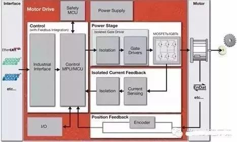
In embedded development, the control of the motor is often involved, and the current frequency conversion control of AC motors is widely used, so let's briefly look at the diagram to introduce the next inverter, assuming that you have understood the principle of the motor.
The block diagram is as follows:

The frequency converter is mainly composed of rectification (AC to DC), filtering, inverter (DC to AC), brake unit, drive unit, detection unit, microprocessor unit, etc. The inverter relies on the internal IGBT to adjust the voltage and frequency of the output power supply, according to the actual needs of the motor to provide the power supply voltage it needs, so as to achieve the purpose of energy saving and speed regulation, in addition, the inverter has many protection functions, such as overcurrent, overvoltage, overload protection and so on. With the continuous improvement of industrial automation, frequency converters have also been widely used.
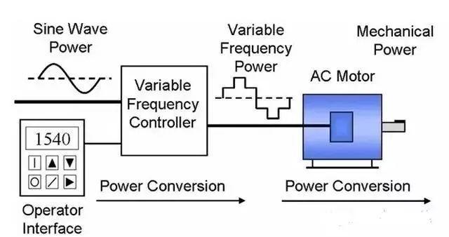
A typical inverter system diagram is shown below. Mainly including, operation panel, VFD controller, motor and other parts

1. Typical structure:
Mainly including: control platform, measurement circuit, power circuit, protection circuit, etc
There are two types of common frequency converters: voltage type and current type, of which the power inverter part mostly uses power tubes such as IGBT and IGCT.
2. Typical algorithm:
Among them, the control algorithm represented by Siemens is mainly based on coordinate transformation (vector control), and the algorithm represented by ABB can find data acquisition by themselves (direct torque control), which is not repeated here.
3. Vector control:
Many chip MCU, MPU manufacturers have given block diagrams and algorithm libraries for frequency conversion vector control, and those who are interested can study and study, such as the block diagram given by Microchip Technology in the figure below


Hotline:000-0000-0000
Tel:130 0000 0000
Email:22@22.cn
Address:Hangzhou West Lake District Zixia Street Internet Innovation and Entrepreneurship Park


